How to make a 220V power supply from an uninterruptible power supply. How to make a power supply from an uninterruptible power supply with your own hands? Converting an uninterruptible power supply for charging
I practically bought myself a 350W uninterruptible power supply from a computer for free. I always wanted to make a powerful 10A 12V power supply from it, after all, a transformer is more reliable than a pulse generator. And since such an opportunity presented itself, why not take advantage of it?
The assembly process took about five hours, and the entire assembly lasted two months. Two months ago I bought an uninterruptible power supply
The first step was to remove the transformer. And the resistance of the network windings was checked. The black wire is the beginning of the winding, the blue wire is the end of the winding, and the red wire is the tap. 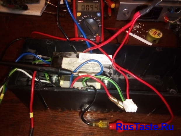

When I decided on the mains winding, I decided to supply power between black and red, then the output power will be slightly higher, and the no-load current will be higher. Naturally, this will lead to additional heating of the windings, but I will have forced cooling.
Having considered all possible options for the future power supply, I ordered the necessary components from China and prepared the case so as not to waste time. I moved the transformer from its original place and secured it to the bottom with four M4 screws, where the trans stood. installed a radiator for the future diode bridge. I also cut a hole for the fan in the back of the case.  About a month later, a pulsed step-down converter for XL4016 12A 0-32V arrived, here is a link to it. Why did I bother to take a photo before remaking the converter, so I’ll explain what I did.
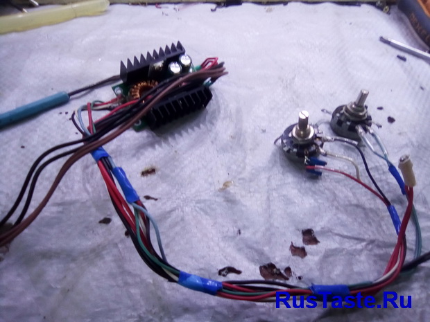
Instead of native trimming resistors, Soviet resistors were installed. For the voltage regulator, the resistor is set to 4.7 kOhm, I will bring it out with two wires to the front panel. This rating makes it possible to regulate the voltage within 1.2V-18.5V. For the current regulator, I installed a 1 kOhm variable resistor, and added a 25 kOhm resistor along the positive wire, which makes it possible to regulate the current within 0-10A.
Also, instead of the block, I soldered wires, wires 0.75 mm square. twisted in pairs to increase the cross-section.
Another month later, literally yesterday, the rest of the components arrived and I got to work. Again, there are no photos of the process, so I’ll go through the finished device.
There were two regulators on the front panel: current and voltage. A 10A type 91C4 ammeter, an electronic voltmeter and terminal blocks left over from the previous one were installed. I also brought out a voltage stabilization indicator LED from the board. 

In the rear part, an XL4016 converter board is installed on the partition, a KBPC5010 diode bridge is installed on the radiator, and a 35V 4700 uF capacitor is glued to the case. The capacitor is needed to filter the mains voltage, after the bridge with it the voltage was 22V.
To power the fan and voltmeter, I used an additional winding from a transformer and installed a diode bridge with a 2200 uF capacitor. After the 25V diode bridge, this voltage is suitable for powering a voltmeter, but this is too much for powering a fan, so the fan will be powered through two parallel 470 Ohm 2 W resistors. The bridge with the condenser was secured with a canopy.
By the way, to protect against any cases :) I installed a fuse on the side panel. 
 This entire assembly took only 5 hours, we can say that everything was assembled in an evening.
Now it’s time to move on to testing this device, well, first, I’ll see how accurate the voltmeter is.
I chose the main voltages for charging different batteries, the first will be the voltage for LI-ION 4.18 V. The voltmeter showed 4.16 V, which is quite normal for a Chinese voltmeter. 
I chose the following voltage for three lithium batteries, here the voltmeter showed 0.1V more, which is also not so bad.  The last voltage is 14.4V for lead batteries. Also an error of 0.1 V, but again acceptable.
  Well, I’ll check the ammeter, although it pleased me much more than the voltmeter.
  Stop fooling around, it's time to load up. What will happen to the unit if there is a short circuit?
  Well, now I’ll load everything with nichrome, I managed to load it at 6A at 15 V
 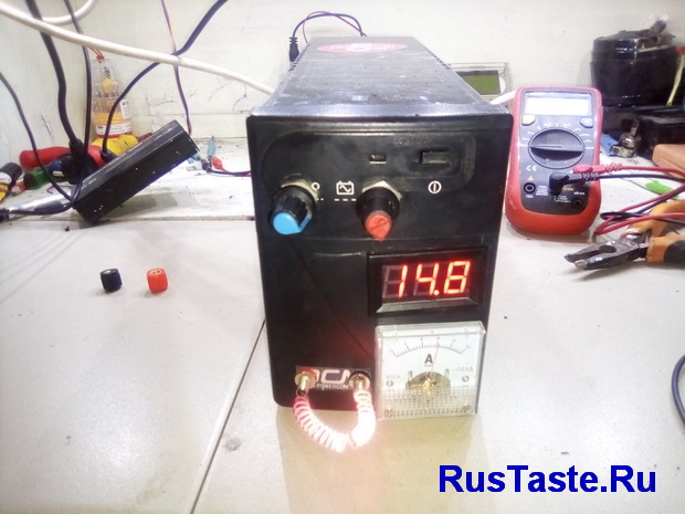 I won’t load it for long because I’ll melt the body. But for about 10 minutes everything was heating up without any problems for the case
The last thing left to do for this power supply is to connect the wires with terminals. I once bought such a wire for 300 rubles.  This completes the assembly and the last thing I need to do is draw a power supply diagram for you
And also add links to all used components
Converter for XL4016 12A 30V costing 290 rubles
Diode bridge 50A 1000V for 100 rubles
Voltmeter 100V for 60 rubles
Ammeter 10A for 130 rubles
Terminal block 4 pieces for 100 rubles
Considering that the uninterruptible power supply itself cost 500 rubles, plus additional parts and so on, my power supply from the uninterruptible power supply cost me 1,500 rubles
Well, that’s all for now, if you like my homemade products and don’t want to miss new ones, subscribe to updates in In contact with or Odnoklassniki
Don’t want to delve into the routine of radio electronics? I recommend paying attention to the proposals of our Chinese friends. For a very reasonable price you can purchase quite high-quality chargers

A simple charger with an LED charging indicator, green battery is charging, red battery is charged.
There is short circuit protection and reverse polarity protection. Perfect for charging Moto batteries with a capacity of up to 20A/h; a 9A/h battery will charge in 7 hours, 20A/h in 16 hours. The price for this charger is only 403 rubles, free delivery

This type of charger is capable of automatically charging almost any type of 12V car and motorcycle batteries up to 80A/H. It has a unique charging method in three stages: 1. Constant current charging, 2. Constant voltage charging, 3. Drop charging up to 100%.
There are two indicators on the front panel, the first indicates the voltage and charging percentage, the second indicates the charging current.
Quite a high-quality device for home needs, the price is just RUR 781.96, free delivery. At the time of writing these lines number of orders 1392, grade 4.8 out of 5. When ordering, do not forget to indicate Eurofork
Front panel of the unit
Back panel

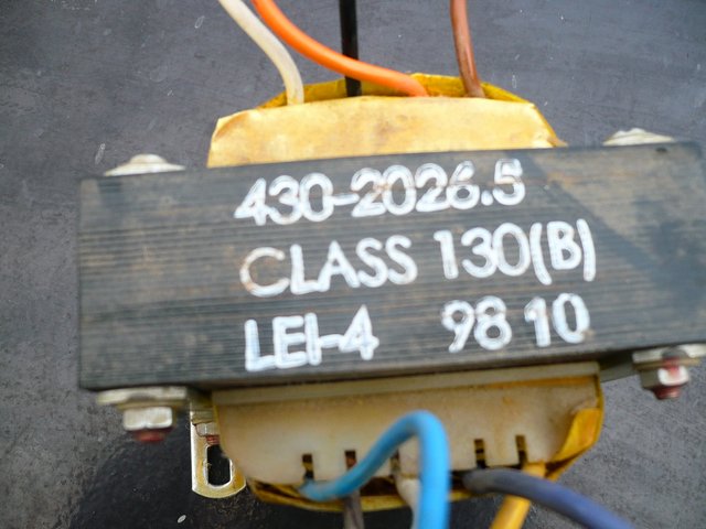
The transformer itself

Its dimensions are 100 x 80 x 80 mm. Weight 2.2 kg. Upon inspection, no visible damage was found. One winding is visible under the insulation, a fairly thick wire, about 1.5 square meters. mm maybe thicker. I found the winding with the highest resistance of this transformer, it turned out to be 12.6 Ohms. The wire color is white + black, on one side of the core. I applied 220 V to them for a short time - nothing - no hum, no smoke - already good. I found a secondary on the other side of the iron with a maximum voltage of about 15 V. The color of the wires is white + yellow.
I had a 50 A diode bridge. I connected it through the original connectors, you can clearly see it in the picture. Next, I connected a 12 Volt 35 Watt halogen lamp to the diode bridge.

The voltage under load dropped to 13 Volts. The output voltage of the diode bridge is 14 V, without load.

Current under load - 3.3 Amperes. The lamp was turned on for about an hour. After that, I checked the temperature of the transformer winding by hand - it was completely cold. I think it will pull more current, but I was too lazy to check. So, it is quite possible to make quite powerful and high-quality power supplies or chargers from uninterruptible transformers. Author: Volodya (skrl)
Uninterruptable power source - irreplaceable thing. Moreover, it and its components can be used in very different ways. From an old uninterruptible power supply or its parts you can easily get:
- inverter;
- Charger;
- power unit.
As for the power supply, using an old uninterruptible power supply you can make both a simple block and a laboratory one. Naturally, a laboratory power supply is much more difficult to assemble, install, mount and configure, and will also require a larger number of additional parts and tools. However, their manufacture is based on the same principle, and the same problems arise when using them.
First, let's start looking at a simple power supply and a diagram for its manufacture from an old UPS from a computer.What will you need?
To make a simple power supply from an uninterruptible power supply with your own hands will be required:
- transformer from uninterruptible power supply;
- case - both an old UPS case and a self-made case for creating a power supply will do;
- diode bridge.
When performing work, you must have basic knowledge of physics and electromechanics, as well as follow safety regulations, use protective clothing and use dielectrics.
As for a simple power supply, most are faced with the same difficulty: the typical voltage value at the outputs from standard transformers is 15 V.
When a load is connected to the resulting power supply, it “sags,” so the required voltage is selected experimentally.Step-by-step algorithm of actions
Algorithm of actions to make your own power supply from an old UPS it will be as follows:
- the transformer is disconnected from the UPS, the future housing of the device is prepared;
- using an ohmmeter, the winding with the highest resistance value is determined: black and white wires, which in the future will serve as the input to the device (if an old UPS case is used for manufacturing, then the input will be the corresponding socket located at the end of the uninterruptible power supply and serving for connection between the device and the socket);
- an “input” is formed from wires located on one side of the core, and an “output” of the device is formed from wires located on the opposite side;
- the transformer is supplied with alternating current with a voltage of 220 volts;
- voltage is removed from unused contacts;
- a pair is determined that has a potential difference of 15 volts (white and yellow wires are “output”);
- a diode bridge is installed at the “output”;
- Consumers connect to its contacts.
Every car owner at some point faces the question of how to charge a dead battery. He also appeared in front of me one day. And it happened, as always, unexpectedly, on a day off, in the village, and as luck would have it, no one nearby had anything similar to charging. I had to strain my brains and quickly make a simple but powerful charger from available materials. And the burnt UPS, an uninterruptible power supply for computers, helped me with this. Without going into deep details, I’ll just note that this device powers the computer from the built-in 12-volt battery in the event of a power failure in the outlet.
From a broken uninterruptible power supply we take the most important thing - a powerful transformer, which usually remains intact; we don’t need all the other spare parts from it.

So, to make a simple charger you will need:
1. Transformer from a burnt-out uninterruptible power supply
2. Diode bridge (rectifier) 2-4 pcs.
3. Capacitor 100...1000 uF with a voltage of at least 25 V
4. Medium-sized radiator
5. Plank, plywood, plastic
6. Thermal paste KPT-8
7. Tester
8. Soldering iron, pieces of wire


Using a tester, we determine the winding terminals that have a higher resistance (from 10 to 50 Ohms), this will be a 220 V network winding. The terminals of the 12V secondary winding are thicker, it is wound with a thicker wire, so the resistance of the secondary winding is almost zero.
The pins that went to the output connectors of the uninterruptible power supply will now be connected to the network, and the wires through which 12V was supplied from the board will be connected to the rectifier.
You will also need several rectifier diode bridges GBU406, GBU 605, GBU606, and a filter capacitance, a capacitor from 100 to 1000 uF for a voltage of at least 25V (from a burnt-out computer power supply). A small radiator for diodes will also come in handy. Of course, you can make a rectifier using ordinary diodes with a maximum current of at least 10 A and a reverse voltage of at least 25 V, but at that moment they were not at hand, and later I also used ready-made rectifier bridges, because they are convenient to mount on a radiator . The rectifier bridges are stacked, coated with heat-conducting paste and pressed to the radiator with a long bolt. All pins of the same name are connected in parallel. Pros with pros, cons with cons, etc.

A transformer, a radiator with diodes are attached to a suitable size wooden plank, plywood, or piece of plastic, the entire circuit is mounted, a cord with a plug from an old soldering iron is connected - and charging is ready!
The mounting options and layout of the charger components can be any, based on what is at hand.


With a rectified output voltage of about 18 V, the charger freely provides a current of up to 5 A. A regular battery is charged in an hour, a very low one - in 3...4 hours. Many motorists in our village now have such a charger.
Moreover, to better charge the batteries, I came up with the idea of connecting the charger in pulse mode. Pulse, of course, is a strong word, it just means that it is connected to the socket through an electromechanical time relay.
This is a simple daily electromechanical relay, it comes from the Middle Kingdom and is sold in the store for 150 rubles.